MR3. FLYING TESTBED.
A flying testbed for developing technical solutions and calculation methods for future high-speed multirotor UAVs.
OVERALL LAYOUT
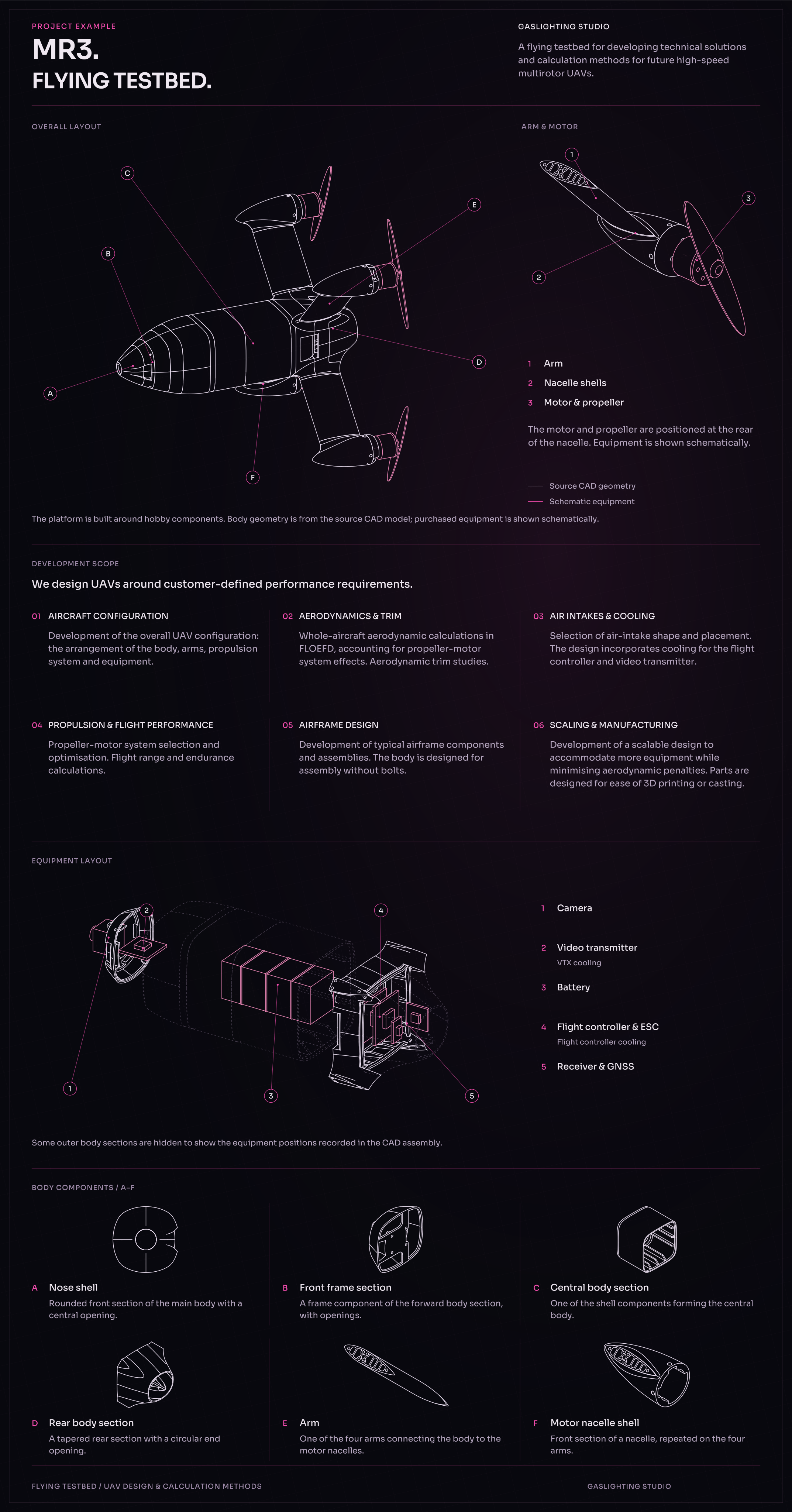
The platform is built around hobby components. Body geometry is from the source CAD model; purchased equipment is shown schematically.
ARM & MOTOR
The motor and propeller are positioned at the rear of the nacelle. Equipment is shown schematically. 1: Arm; 2: Nacelle shells; 3: Motor & propeller.
DEVELOPMENT SCOPE
We design UAVs around customer-defined performance requirements.
AIRCRAFT CONFIGURATION
Development of the overall UAV configuration: the arrangement of the body, arms, propulsion system and equipment.
AERODYNAMICS & TRIM
Whole-aircraft aerodynamic calculations in FLOEFD, accounting for propeller-motor system effects. Aerodynamic trim studies.
AIR INTAKES & COOLING
Selection of air-intake shape and placement. The design incorporates cooling for the flight controller and video transmitter.
PROPULSION & FLIGHT PERFORMANCE
Propeller-motor system selection and optimisation. Flight range and endurance calculations.
AIRFRAME DESIGN
Development of typical airframe components and assemblies. The body is designed for assembly without bolts.
SCALING & MANUFACTURING
Development of a scalable design to accommodate more equipment while minimising aerodynamic penalties. Parts are designed for ease of 3D printing or casting.
EQUIPMENT LAYOUT
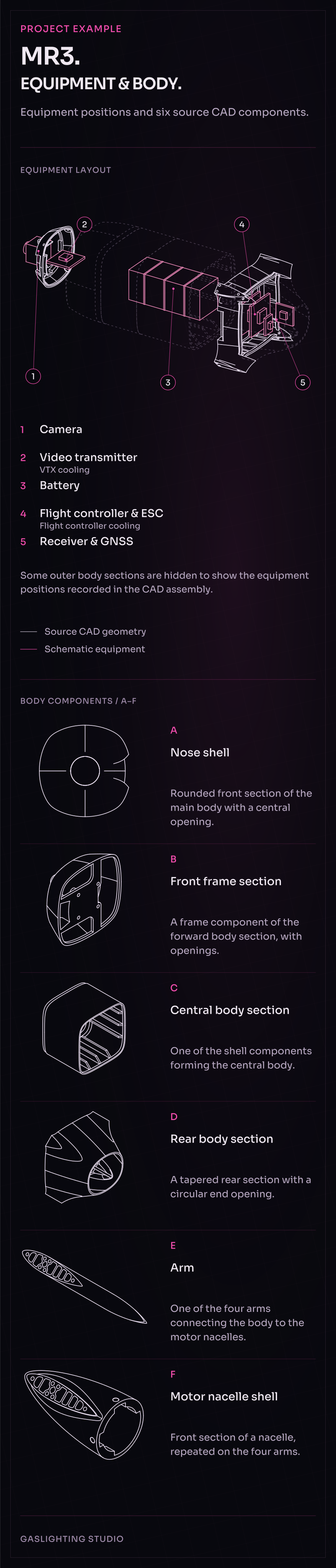
Some outer body sections are hidden to show the equipment positions recorded in the CAD assembly. 1: Camera; 2: Video transmitter — VTX cooling; 3: Battery; 4: Flight controller & ESC — Flight controller cooling; 5: Receiver & GNSS.
BODY COMPONENTS / A–F
Equipment positions and six source CAD components.
A / Nose shell
Rounded front section of the main body with a central opening.
B / Front frame section
A frame component of the forward body section, with openings.
C / Central body section
One of the shell components forming the central body.
D / Rear body section
A tapered rear section with a circular end opening.
E / Arm
One of the four arms connecting the body to the motor nacelles.
F / Motor nacelle shell
Front section of a nacelle, repeated on the four arms.